Coax Noise Filters
The Problem:
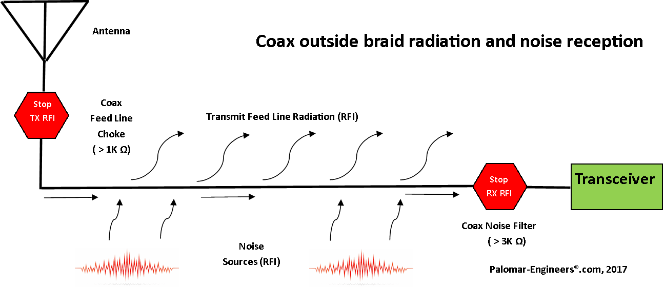
Common mode current induced by radiated sources (plasma TV, routers, computers, transmitters, etc.) can be picked up by the outside of the coax braid from the antenna feed point back to the receiver. This portion of the coax braid acts like a second receiving antenna, picking up common mode noise signals that combine with weak signals (traveling down the center conductor and inside of the coax braid) making it difficult or impossible to hear weak signals! See diagram below.
The Solution:
A coax common mode noise filter with high choking impedance at the receiver/transceiver end of the coax effectively reduces common mode noise present on the coax braid while passing desired signals present on the coax center conductor. For best results, and to reduce co-interference between choked and un-choked feed lines with multiple antennas, EACH antenna feed line entering the radio room needs to have a coax noise filter even if it feeds a common coax switch since most antenna switches ONLY switch the center conductor of the coax line, yet all the coax braids are ALWAYS connected together in parallel.So when an antenna is NOT SELECTED, its coax sheath still contributes to the noise level of the connected antenna through the common connector ground!
The solution? A common mode noise filter with high choking impedance at the receiver end of the coax.
Do you have common mode noise on your coax?
Make this simple test to find out.
- Remove the coax connector and measure the noise level.
- Now insert the coax connector CENTER CONDUCTOR ONLY into the SO-239 antenna input and measure the noise level (it should be higher and include possible signals)
- Now connect the OUTER SHELL of the coax connector to the antenna input and measure the noise level.If it is higher you have common mode noise and the common mode noise filter will help suppress this noise which is carried on the outside of the coax braid (acting as a second receive antenna).
Common mode noise suppression with the Palomar CMNF series of filters is typically 25-36 dB which is equivalent to 4-6 “S” units on radios with 6 dB/”S” unit or may be more on radios with 3dB/”S” unit.
Note for antenna switch users, perform the above test on each antenna coax lead separately to determine if that particular antenna braid is contributing noise to the receiver – use a coax noise filter on the antennas that have common mode noise.
Coax Common Mode Noise Test (pdf)
A simple ferrite ring filter on the DC power line can help suppress the RFI noise affecting the victim device or keep the DC power cord from acting as an antenna and radiating RFI into other victim devices. This kit is also useful on laptop computer supplies, routers, cable modems, wireless phone charges, etc.

Installation is quick and easy: Just wrap the DC power cord through the center of the ring filter as many times as you can and reinstall. For best results with long DC power lines, use one at the ring filter at the wall wart end (to prevent the wall wart power supply from using the DC line as an antenna) and another at the DC plug end (to prevent the electronics in the powered device from using the DC power cord as an antenna). Typical installation is shown below:
The filter suppresses RFI in from .1-100 MHz. Inside diameter is 3/4 inch/19 mm.
Since most households and office environments have multiple wall warts we offer the Wall Wart RFI Filter kit in bulk quantity packages.
Known RFI Generators include Roku/Sling-TV power adapter - Interference heard in the AM broadcast band
 and harmonics.
Also many ethernet Cable/DSL modems, cell phone chargers, computer power adapters have the same issue:
using the AC or DC side of the power supply as a radiating antenna.

RFI solution is to use a linear power supply, change adapters or wall wart ferrite filters


