One of the most popular antennas today is the end fed long wire antenna due to it ease of installation, portability and stealth in various installations. It can be a condo dweller’s only access to the world of ham radio or the best alternative for a backpacking SOTA (Summits on the Air) mountaintop expedition.
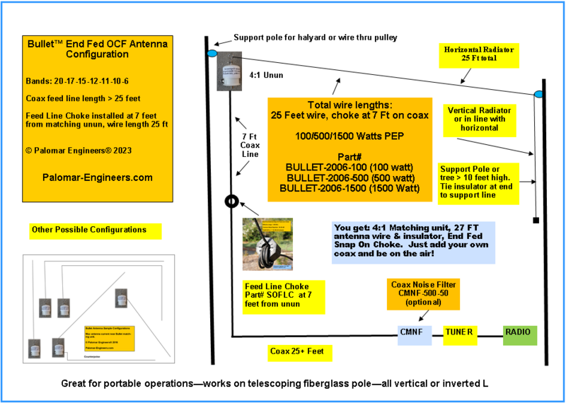
The antenna is simple to deploy, folds up easily for transport, and weighs under a pound, yet, with the proper length of wire, can work the 80-10 meter bands easily with the built in antenna tuner of most current day transceivers. You will need several components for a successful deployment of the end fed antenna and these are shown in the diagram below:

 The antenna impedance matching components (BOX “Z” above) to match the antenna impedance to the coax line impedance (usually 50 ohms). For non-resonant end fed antennas, the typical feed point impedance is 300 to 600 ohms and a 9:1 impedance transformer (e.g. 450 ohm average antenna impedance to 50 ohm coax, also know as a 9:1 unun). For do-it-yourself antenna builders, 9:1 impedance transformer information is HERE
 With end fed antennas, the coax is meant to radiate as part of the antenna system (serving as the “ground” or counterpoise) and therefore you need to use a Feed line Choke (BOX “FC” above) to suppress the common mode current on the outside of the coax feed line so it does not enter the radio and cause garbled communication.. The Feed line (FC) acts as a stop sign for RF current flowing back on the outside of the coax. The higher the choking resistance of the feed line choke, the less the coax braid RFI common mode current, and the less noise enters the radio. Feed Line choke alternatives are HERE.
 The radio station is also a key component of the antenna system and has two functions: transmit and receive. Matching the transmitter to the coax feed line is often done with an antenna tuner and receiver systems should be installed to maximize signal to noise ratio. Reducing receiver noise is critical for weak signal reception and the use of coax noise filters AND receiver power supply lines (AC or DC) noise filters is usually needed for optimum reception. Reducing RFI generated by the radio station (you are the SOURCE of RFI) or received by your radio station (you are the VICTIM of RFI) is an important aspect of radio station operations. Palomar Engineers has many solutions for RFI problems – Click HERE to develop alternative strategies depending on your particular situation.
Want to compare End Fed Antennas? See: End Fed Antenna Secrets (PDF)
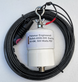
The “Bullet” End Fed Long Wire Antenna
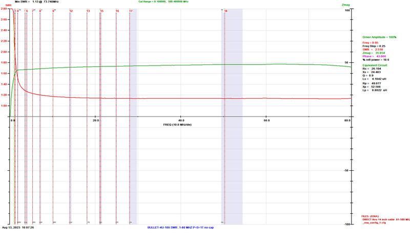
The key to end fed antenna success is the matching network interface between the long wire antenna and the coax feed line and feed line choke at the transceiver. Palomar Engineers employs a dual core matching system that offers wide bandwidth (1-61 MHz), 500 watt PEP rating, and a connection for a counterpoise or ground if desired.
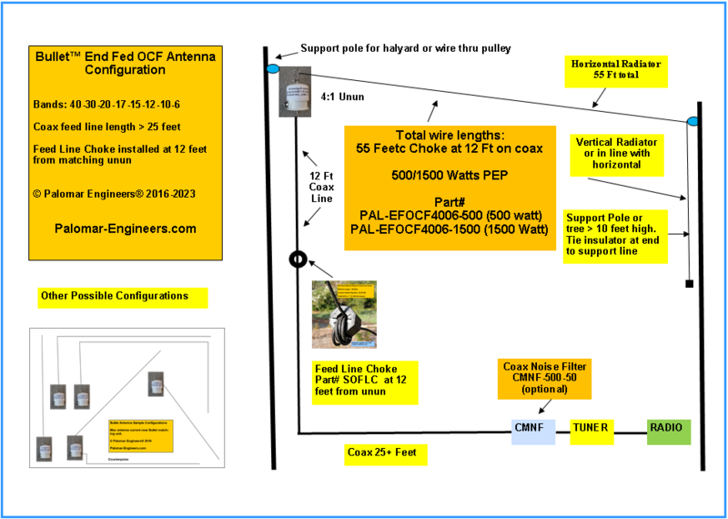
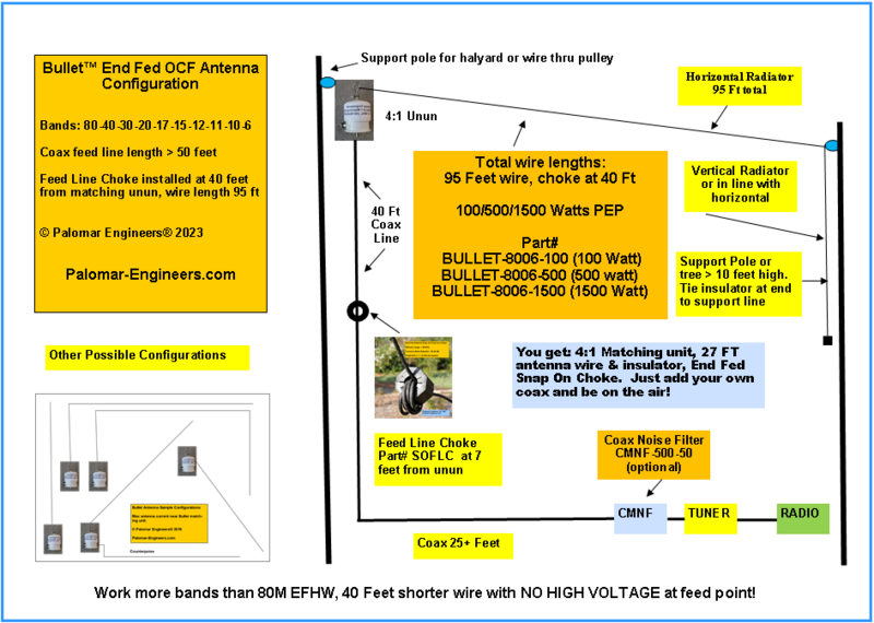
The antenna can be used as a sloper, “L” with a vertical section and a longer horizontal section, or as a random horizontal antenna between two trees or supports.
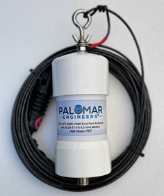
Our network matching network is called the “Bullet” because of it shape and its effectiveness at taking down or contacting distant (DX) stations all over the world under the right conditions. The Bullet uses all stainless steel connectors and a dual core ferrite 9:1 unun for higher power rating then many competitive products.
We sell the Bullet components separately so you can add you own wire type and length or you can purchase a complete antenna system including wire and end insulator.
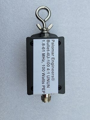
 HF Unun, 1.8-61 MHz, 100/500/1500 Watts, End Fed OCF Antennas")
Bullet 50:200 (4:1) HF Unun, 1.8-61 MHz, 100/500/1500 Watts, End Fed OCF Antennas
The “Bullet” End Fed OCF Antenna Matcher - 100/500/1500 Watts PEP/Digital
The key to end fed OCF antenna success is the matching network interface between the wire antenna and the feed line choke on the coax. Palomar Engineers employs a dual port ferrite matching system that offers wide bandwidth (1.8-61 MHz), and a 100 watt PEP power rating.
The antenna can be used as a sloper, “L” with a vertical section and a longer horizontal section, or as a horizontal or sloper antenna between two trees or supports. Great antenna for portable operations like NPOTA, SOTA, Field Day, etc., or for permanent installations like installing in an attic, under the eaves of a house, along a fence, etc. This is a short, effective and easy-to-hide antenna which gives a good account of itself on -80-6M (95' wire, 40' counterpoise using coax or wire), 40-6 (55' wire, 11' counterpoise using coax or wire) or 20-6 (25' wire, 7' counterpoise using coax or wire,).
Note: To use a separate wire as the counterpoise (or as an additional counterpoise besides the coax and choke), you need to specify the counterpoise stud option when ordering. DO NOT PUT A CHOKE UNDER THE BULLET-4U-100 transformer unless you add the stud option and use a wire as the counterpoise! These antennas are tuned as off center dipoles meaning they need 2 wires - antenna wire and coax counterpoise down to choke or antenna wire and separate wire connected to a counterpoise stud.
We sell the Bullet-4U-100 separately so you can add you own wire type and length or you can purchase a complete antenna system including wire and end insulator. Remember you also need a feed line choke like the easy adjustable snap on SOFLC. Note: Wire shown in product pictures is NOT INCLUDED but shown for illustrative size purposes. Wire kits can be purchased separately if needed. Need BNC input, add the UHFMale to BNC Female adaptor, UHFMBNCF,
If you need a higher power 4:1 unun for your OCF end fed antenna, check out the Bullet-4U-500 or Bullet-4U-1500.Use a good quality 50 ohm cable such as RG-8X or similar as that size allows multiple (5-6 recommended) turns thru the feed line choke. The Bullet-4U-100 matching unit is rated for 100 watts PEP for SSB and 100 watts for CW/FT8. If the matching unit becomes warm to the touch after transmitting at high power, reduce the power output or the internal matching unit may become damaged.
NOTE: We rate our Bullet baluns (and ununs) VERY conservatively with a 50% duty cycle as used with digital (FT8) modes. Some manufacturers selling low cost baluns may use a 5% duty cycle for their PEP rating to make it appear you get a higher rated balun for a lower price, but you may in fact be getting be getting less. Their 1500 watts PEP really means 75 watts continuous or 150 watts at a 50% duty cycle compared to our 250 watts at 50% duty cycle. Our baluns typically cover a larger frequency range under 2:1 SWR which make your transceiver happy and probably will last longer with less electrical stress.
Remember we over engineer our products, to out perform our competition - just compare the weight of our products and the bandwidth SWR to theirs and you will know we put much more into our products so you don't have to worry about power saturation failure at a critical moment.


")

Typical installations are shown below:
Bullet End Fed Antenna Notes (PDF)
CAUTION
USE CAUTION WHEN INSTALLING ANTENNA AND KEEP AWAY FROM ANY POWER LINE WIRES!