Here are some typical OCF dipoles that are successful designs
160-6 meter Double Off Center Fed antenna layout
(using a double tuned stub for better 20/40 meter performance)

Here is the 160-6 meter SWR graph using 200 feet of RG213 feed line and an average height above ground of 35 feet:

Palomar Engineers PAL-OCF1606 Manual Antenna 2021 Version
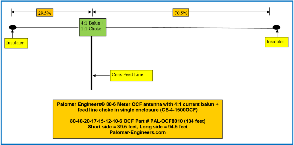
80-10 meter OCF antenna layout
 For the PAL-OCF8010 with 250 feet of RG213 feed line and an average height of 30 feet:

Palomar Engineers PAL-OCF8010 Antenna manual 05242021 29.5-70.5
For the PAL8010OCF, the impedance is very well behaved in a limited, easy to match range throughout the 1-54 MHz range and, in fact, that antenna also works very well on 6 meters with very good gain. Super convenient and quick – great for contest operation!
It is well worth the effort to use the 80-10 OCF if you have the room as SWR’s are less on many bands and you do get the use of 75/80 meters also. (antenna tuner may be needed to use both ends of 80 meter band).
40-10 m OCF antenna layout

On 40-20-17-15-12-10 meter models we use a resonance compensator to pick up the 15 meter band not present on many competing OCF antenna products. We have complete OCF antennas and also the impedance transformers and chokes as separate products (see below for various options with and without vertical radiators).
For the PAL-OCF4010 with 100 feet of RG213 feed line and an average height of 30 feet:

Palomar Engineers PAL-OCF4010 Antenna Manual
No vertical radiator is used in the OCF antenna. Note that if you want to use a vertical radiator (ala Carolina Windom), then you will need to use a 4:1 voltage balun rather than a current balun so that some of the RF fed to the antenna feed point will go down the feed line through the vertical element and give some vertical polarized output. At the bottom of the vertical element you will need a feed line choke with high choking impedance to stop the current from going down the rest of the coax back to your radio and causing RFI with the neighbors and getting into your radio room. At the radio end of your coax line add a common mode noise filter (CMNF-500, -1500, or -5000) to remove the common mode noise picked up by the coax braid as near field radiation from the antenna and neighborhood devices.
Here is a layout and SWR curve for our OCF with vertical radiator for 80-6 meters:

SWR Curve for the Vertical Radiator OCF (part# PAL-OCFVR8006-1500):

INSTALLATION
For best results support center at 30+ feet and ends over 15 feet. Angle of feed each side must be great than 45 degrees or 120 – 180 degrees total between each side preferred. Any length of 50 ohm feed line ok but longer feed lines over 50 feet may show reduced SWR on some bands due to losses in feed line and soil conductivity, nearby objects, etc. Due to local ground conditions, antenna height and feed line length, SWR may vary from samples shown and an antenna tuner may be required or some bands to bring SWR at end of feed line to acceptable levels.
For quieter receive signals, don’t forget a good quality choke at the radio end of the coax. Use our MC-1-3000 Maxi-Choker or Coax Noise Filter CMNF-500/1500/5000 depending on power in the coax line.