Broad Band Terminated Dipoles (BBTD, T2FD)

Broad Band Terminated Dipoles (BBTD), Tilted Terminated Fold Dipoles (T2FD) and Balanced Termination Folded Dipole BTFD) antennas can be designed to cover a large range of frequencies between 1.8 30 MHz.  Longer length antennas generally provide better low frequency efficiency but take up a larger footprint of land.   One BBTD that has worked well at the AK6R antenna farm is shown below.  Many other designs are available and can be found at www.HFLINK.COM as well as other internet sites.  Your mileage may vary using this antenna, but as a general coverage antenna for ham and shortwave broadcast, the simplicity can’t be beat even though an individual dipole on a specific band may out perform this broad band dipole.  Palomar Engineers has all the parts you need to build this antenna, so why not give it a try?

BBTD at AK6R 1024x726 - Broad Band Terminated Dipoles (BBTD, T2FD)


Depending on the source of the antenna design, different value baluns are specified.  Our Bullet(TM) baluns in ratios of 9:1, 12:1 and 16:1 are excellent for this type of antenna as they are broadband from 1.8-61 MHz and will take up to 500 watts PEP.

Solar Power Optimizer/PV Module Noise Filters (2) - ID=1.4"

SKU RFI-PV-PO
$24.95
2
$12.48
Bulk pricing available for quantities of 10 units or more
1
Buy more, save more
QuantityPrice per itemDiscount
10 items$21.9512% off
50 items$19.9520% off
100 items$18.9524% off
Save this product for later
Customer reviews
No reviews yet. Only signed-in customers who bought this product can leave reviews. To leave a review, sign in
Share this product with your friends
Solar Power Optimizer/PV Module Noise Filters (2) - ID=1.4"
Product Details
MPN: RFI-PV-PO
Type: New
Country/Region of Manufacture: United States
Filter Power Rating (PEP watts): not applicable
RFI Suppression Range (MHz): .1-10
# Ferrite Filters: 2
Enclosure Size (inches): none

The RFI kit is designed to suppress RFI caused by Solar micro-inverters, power optimizer, and solar arrays by electrically isolating the “antenna” wires used to connect the various devices.The cabling between the PV array, the micro-inverters or power optimizers and their connection to the electrical bus combining their individual outputs can be considered “antennas” for the pulse switching circuits of the individual devices thereby causing radiation at very low fundamental frequencies with harmonics that can cause undesirable radio interference in the 1-30 MHz (and sometimes higher) frequency range.This interference may be objectionable to the owner of the solar installation as well as neighbors who may also experience the interference to their electronic devices.

THE RFI KIT FILTERS ONLY SUPPRESS COMMON MODE CURRENT (SIGNALS) THAT ARE COMMON TO ALL WIRES IN THE CABLE, AND DOES NOT EFFECT INDIVIDUAL DIFFERENTIAL SIGNALS ON EACH WIRE. THE FILTERS HAVE NO EFFECT ON THE NORMAL SIGNALS CARRIED WITHIN THE CABLE.

Power Optimizer RFI

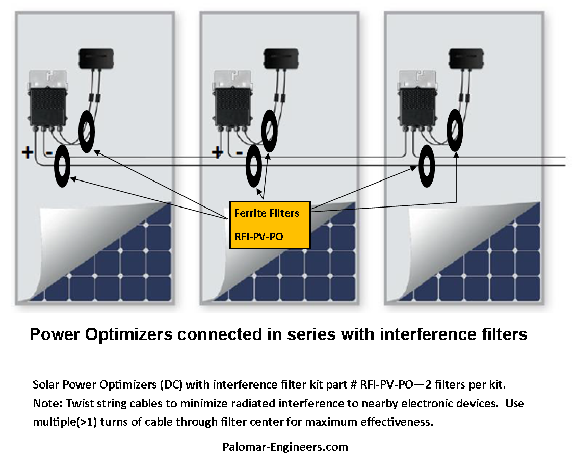
Ferrite cores (slip on) have the two (+/-) cables from the solar array module thru the middle of the core and the two wires hooked to the “string” connecting the optimizers together. Suppressing RFI on all wires in and out of the optimizers helps to reduce any broadband RFI “noise” generated in the SOURCE switching circuits (typically at 200-1000 KHz and harmonics thereof). Two ferrite filters are required for each optimizer – we recommended Part # PV-RFI-PO (includes two ring filters). See typical installation diagram below:

Power Optimizers with filters 2 png - Broad Band Terminated Dipoles (BBTD, T2FD)

Likewise Termination Resistor values vary from 500-1250 ohms and we have a good selection shown HERE: