CUBE Impedance Transformers (<1:1, 1:1, >1:1)
CUBE™ Impedance Transformers
Match your antenna with precision — wide-range baluns & ununs from Palomar Engineers®

Overview
The CUBE™ series impedance transformers from Palomar Engineers® provide reliable broadband matching between 50 Ω feed lines and a variety of antenna loads. Ratios from 1:1 to 16:1 cover dipoles, loops, ladder-line systems, off center fed, end-fed, BBTD and TTFD antennas.
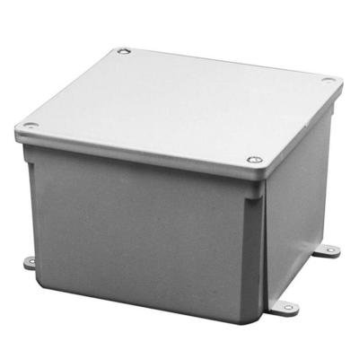
Each transformer features stainless-steel hardware, weather-resistant NEMA enclosures, and heavy-duty windings for continuous HF operation (up to 5 kW PEP, model-dependent). Built and tested in the USA — continuing Palomar’s 65-year tradition of RF excellence.
Why Matching Matters
- Reduces SWR and maximizes RF transfer efficiency.
- Prevents unwanted common-mode currents and RFI on feed lines.
- Improves tuner performance and overall station reliability.
Quick-Selection Guide
Choose the right transformer ratio based on your antenna type or impedance range.
| Antenna Type / Scenario | Typical Load (Ω) | Matching Ratio (Output:Input) | Suggested CUBE™ Model | Notes |
|---|---|---|---|---|
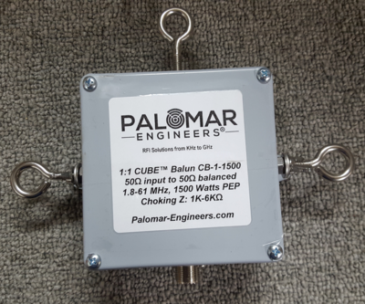
| Standard 50 Ω Dipole | ≈ 50-75 | 1:1 | CUBE™ 1:1 Balun | Ideal for balanced antennas — basic isolation. |
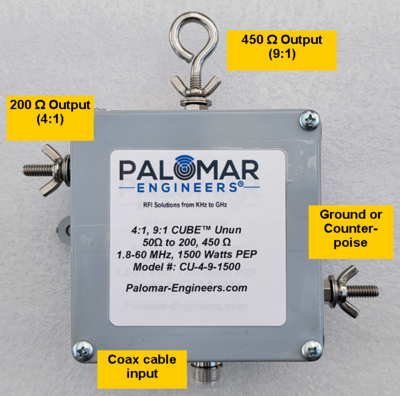
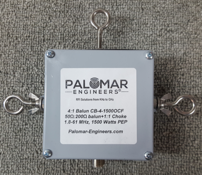
| Multi-Band Full Wave Loop or Off Center Fed Dipole (200 Ω) | ≈ 200 | 4:1+1:1 | CUBE™ 4:1 Balun + 1:1 Choke Hybrid | Use for 200 Ω balanced feed to 50 Ω coax and suppress common mode current on coax |
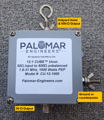
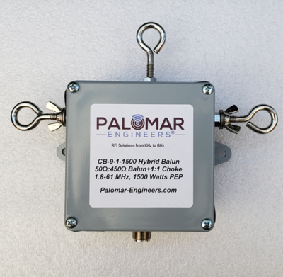
| Ladder-Line Fed Windom (450 Ω) | ≈ 450 | 9:1 | CUBE™ 9:1 Balun | For higher-Z ladder-line loads. |
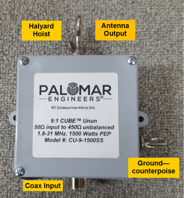
| End-Fed Non-Resonant Long Wire Antenna | ≈ 400-500 | 9:1 | CUBE™ 9:1 Unun | Classic end-fed matching — wideband HF coverage. |
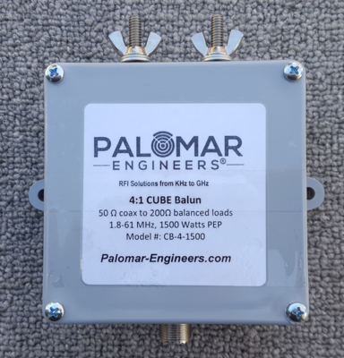
| End Fed Resonant Antenna (~200 Ω) | ≈ 200 | 4:1 | CUBE™ 4:1 Unun | Raises low impedance to match 50 Ω feed line. |
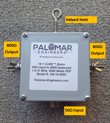
| BBTD, T2FD (450 or 1000 Ω) Balanced | 100–112 | 9:1+1:1 or 16:1+1:1 Hybrid | CUBE™ 9:1+1:1 or 16:1+1"1 Balun | For custom feed systems and high SWR margins. |
Installation Tips
- Choose a transformer rated for your maximum PEP output.
- Mount with the enclosure drain-hole down for outdoor use.
- For extra RFI suppression, add a feed-line choke near the station.

We specify impedance ratios as an output to input ratio where the output (or load) is given first and the input is given second (e.g. 100:50 (2:1) would mean a 100 ohm output and a 50 ohm input; a 25:50 (1:2) would mean a 25 ohm load and a 50 ohm input). Most all products use a 50 ohm input unless otherwise specified.
We have products that are available as kits for the do-it-yourself (DIY) person or fully assembled and tested units for the “Plug & Play” crowd.
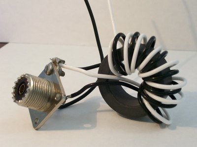
Our impedance transformers are available using two different topologies: Binocular cores or toroid cores with multiple turns for increased effectiveness and wide band frequency transformations. We utilize single and multiple core transformers using high order windings when needed to extend product performance.
We rate the power ratings as watts PEP (Peak Envelop Power) with standard duty cycles for various modes. To determine the PEP rating required for your needs, see: Choke & Transformer Power Ratings
This website page serves as a link page to the frequency ranges of our impedance transformers configured as either baluns or ununs. You can click on a picture to go to the specific page about the products described in the picture.